Fiber: Choosing Fiber Patch Cables Between Speed and Distance
Published by Cablesys on Aug 24th 2017
More fiber patch cables are being deployed into data centers. The need for a green data center and high bandwidth with long distance are some examples driving demand. To determine the appropriate fiber optic cable, two primary layers must be understood, the core and cladding.
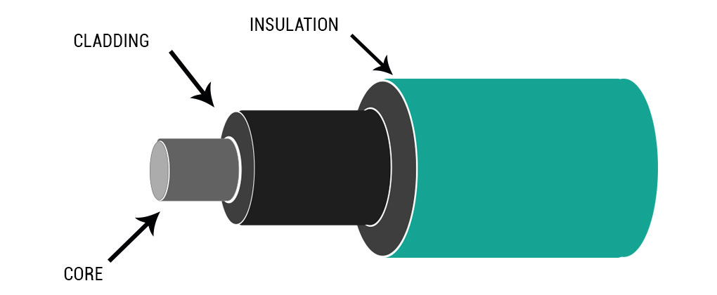
The Core
Within the middle of the optic cable is the core. The core is a cylinder made of glass or plastic. Surrounding the core is cladding which is another type of glass or plastic.
The outer diameter of the core determines how much light transmits within the fiber. A larger core can transmit more light than a smaller core. The core’s cross-section should be circular. The diameter is defined as the average of the diameters of the smallest circle restricted to the core-cladding boundary. Also, the largest circle that can be inscribed within the core-cladding boundary.
Another measurement is the mode field diameter where the maximum intensity of light is defined. The diameter of the single-mode fiber is larger than the core because light enters into the cladding slightly.
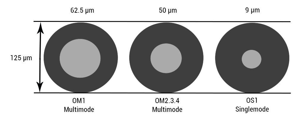
The diagram pictured below shows three common core sizes measured in micron (µm); 62.5/125 (62.5 µm), 50/125 (50 µm) and 9/125 (9 µm) separated into modes. A micron is equal to one-millionth of a meter; 25 microns equal roughly to a sheet of paper. The core of the multimode fiber has a wide diameter of 50 to 100 microns. The most common size is 50/125. Specifying the diameter ratio of the core to cladding is 50 microns to 125 microns. The core of the single mode fiber has a narrow diameter of 8.3 to 10 microns. Specifying the diameter ratio of the core to cladding is 9 microns to 125 microns.
The Cladding
Cladding surrounds the core to keep light within it. The cladding is made of a material that causes a reflection to help light waves continue moving throughout the length of the fiber. In some optical fiber cable, light can propagate within the core as well as the cladding. As a result, cladding supports various refractive indexes and comes in different modes. Modern fibers support a mode within the core. They have a refractive index a little higher than that of the cladding. After a few centimeters of transmission, the light traveling in the cladding is quickly weakened and disappears.
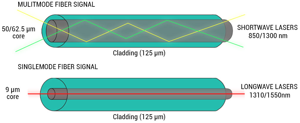
The diagram pictured below shows how the light wave in multimode fiber optic cable disperses into numerous paths. Multiple modes of light are transmitted and reflected through the core. As a result, more data can pass through at the same time. However, because of the increase in reflections, the strength of the signal is reduced over long distances.
Single mode fiber allows only a single mode of transmission. Due to the narrow size of the core, the number of light reflection decreases. As a result, the strength of the signal increases and the light wave can travel a longer distance.
The Coatings
Coatings are usually multi-layers of plastics applied to preserve fiber strength, absorb shock and provide extra fiber protection. These buffer coatings are available from 250 microns to 900 microns.
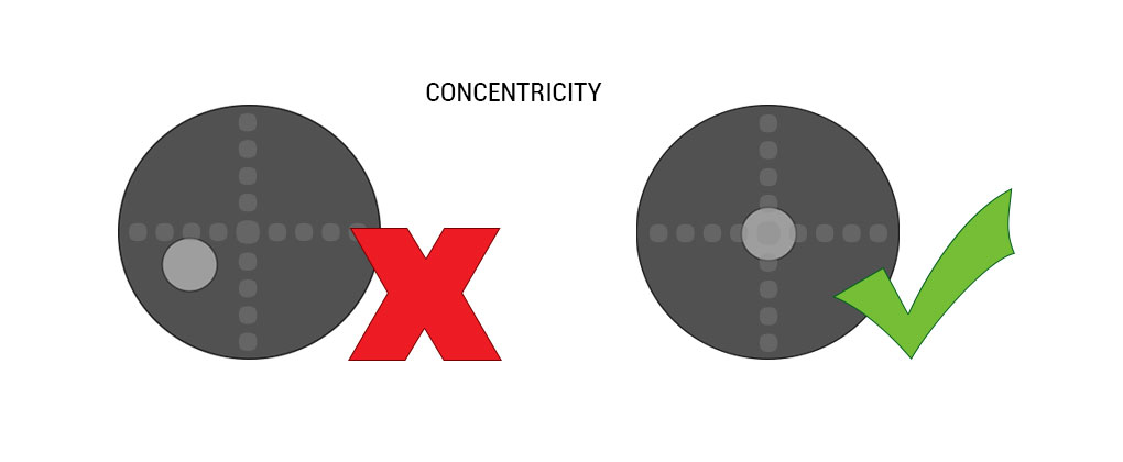
Core-cladding Concentricity
One of the most important elements affecting the loss of a connection between two optical fibers is core-cladding concentricity. The concentricity of optical fiber cores determines the light transmission quality. Tolerances in fiber core to fiber cladding and ferrule edge to ferrule bore can influence the concentricity. Matching the diameter of the fiber to the diameter of the bore can also influence concentricity.
The diagram pictured below shows the core should be as close as possible to the center. Eliminate misalignment and reduce optical loss, the core/cladding offset in Cablesys fiber patch cables are individually inspected not to exceed < 1.5 microns.
Bandwidth vs. Distance
The chart below shows the comparison between fiber optic bandwidth and distance. As the data rate in bandwidth increases, the distance decreases.
| Data Rate |
Fast Ethernet
100BA SE-FX |
1Gb Ethernet
1000BASE SE-SX |
1Gb Ethernet
1000BA SE-LX |
10Gb Base SE-SR | 40Gb Base SR4 | 100Gb Base SR10 | ||
|---|---|---|---|---|---|---|---|---|
| Category | Type | Core | Distance | |||||
| OS1 | Singlemode | 9/125 | 200 meters | 5K meters | 5K meters | 10K meters | Not Supported | Not Supported |
| OM1 | Multimode | 62.5/125 | 200 meters | 275 meters | Not Supported | 33 meters | Not Supported | Not Supported |
| OM2 | Multimode | 50/125 | 200 meters | 550 meters | Not Supported | 82 meters | Not Supported | Not Supported |
|
OM3*
Laser Optimized |
Multimode | 50/125 | 200 meters | 550 meters | Not Supported | 300 meters | 100 meters | 100 meters |
|
OM4*
Laser Optimized |
Multimode | 50/125 | 200 meters | 550 meters | Not Supported | 400 meters | 150 meters | 150 meters |
Singlemode is for distances up to 10,000 meters (over six miles). OS1 provides higher transmission rate and up to 50 times more distance than multimode.
Multimode is usually for short distances that are less than a couple of miles. OM3 and OM4 are laser optimized, also supported by 10 Gb, which allows for longer distances of up to 300 meters (OM3) and 550 meters (OM4).
OM1 (62.5/125 µm) and OM2 (50/125 µm) are the most widely installed in today’s industry. OM1 and OM2 are supported by 10 Gigabit Ethernet at lengths up to 33 meters and 82 meters respectively, and they are the most commonly used for 1Gb Ethernet applications.
Cablesys is a manufacturer of fiber optic patch cables and connectivity. For more detailed information about fiber optic cables, please view them online here: OS1 singlemode patch cables, OM1 multimode patch cables, OM2 multimode patch cables, OM3 multimode patch cables, and OM4 multimode patch cables.